- +86 13512168749
- oversea@zlmcu.com
- Buy Online

关注官方微信


Products


 Single Serial Device Server
Multi Serial Device Server
IoT Chip
P2P Networking Products
Serial Port Ethernet Core Module
Serial Port Ethernet Module
WIFI Products
2G/3G/4G Products
Zigbee/RF Products
Optical Fiber Products
Modbus Gataway
Remote IO Controller
Interface Converter
Single Serial Device Server
Multi Serial Device Server
IoT Chip
P2P Networking Products
Serial Port Ethernet Core Module
Serial Port Ethernet Module
WIFI Products
2G/3G/4G Products
Zigbee/RF Products
Optical Fiber Products
Modbus Gataway
Remote IO Controller
Interface Converter

This article introduces the usage of ZLAN devices supporting MQTT and JSON, including ZLAN5143, ZLAN8303-7, ZLAN1043, ZLAN7144 and so on. The firmware version of ZLAN5143, ZLAN8303-7 and ZLAN1043 should be 1.577 or above, and the firmware version of ZLAN7144 should be 1.489 or above. It needs to be used with version 5.09 of zlvircom.
MQTT and JSON can be used alone or in combination. JSON supports conversion from Modbus RTU format to JSON format.
The main features are:
1) Establish connection with the server using MQTT-based protocol and conduct data communication in the form of subscription and publication.
2) Support independent design and automatic acquisition of Modbus RTU registers.
3) Support to convert specific Modbus register contents into JSON format for timing active upload.
4) Support adding device ID in JSON format to facilitate the identification of devices in the cloud.
5) Support unsigned data and signed data, support decimal point representation, and support 4-byte length data.
6) All the configurations can be completed by interfacial configuration, and users do not need to customize the configuration independently.
ZLAN Modbus RTU to JSON can realize the automatic collection of Modbus RTU table, and automatically send it to the cloud server in JSON format.
Here we illustrate this usage with a concrete example.
Suppose you have a Modbus table with function code 3 and address 1. The register address and parameter name are as follows. Where a byte length of 4 indicates that two registers need to be read consecutively.
| Register address | Parameter name | Byte length | Remarks |
| 0 | Total active power | 4 | Unsigned, keeping 2 decimal places |
| 97 | A phase voltage | 2 | Unsigned, with 1 decimal place reserved |
| 98 | B phase voltage | 2 | |
| 99 | C phase voltage | 2 | |
| 100 | A phase current | 2 | Unsigned, leaving 2 decimal places |
| 101 | B phase current | 2 | |
| 102 | C phase current | 2 | |
| 119 | Frequency | 2 | |
| 356 | A phase active power | 4 | 4 signed, with 3 decimal places reserved |
| 358 | B phase active power | 4 | |
| 360 | C phase active power | 4 | |
| 362 | Total active power | 4 |
Signed means that the maximum bit of 2 bytes or 4 bytes is the symbol bit, for example 0xFFFF will be considered -1. To keep 2 decimal places is to move the decimal point 2 places from the rightmost to the left after converting the data as an integer.
We configure the device as a Client.
Using SocketDlgTest (http://www.zlmcu.com/document/tcp_debug_tools.html), to monitor a TCP server on the local computer port 1883.
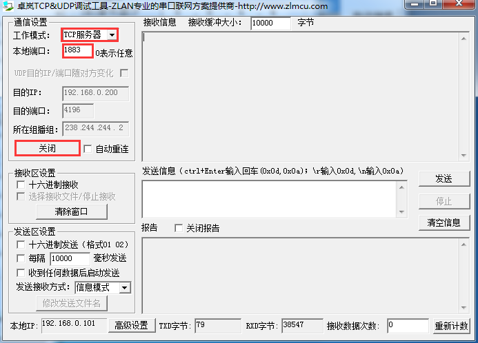
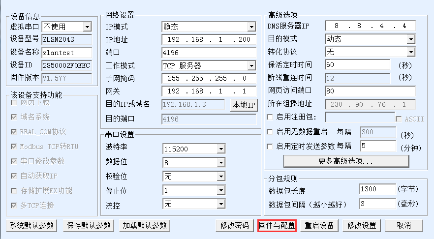
Configure the device using ZLVircom5.09.
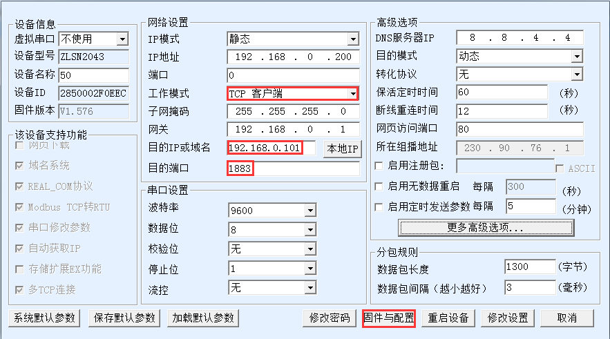
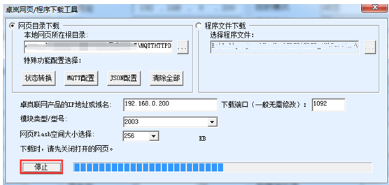
Click modify configuration to connect the device to the SocketDlgTest tool. Enter the device edit dialog again. Click the "firmware and configuration" button.
First click "web directory download" to enter the configuration download mode. Then select a new empty directory, such as the MQTTHTTPD directory. To prevent residues in the previous design, please click the "clear all" button first to clear the previous design content. The design file will be saved in this directory and can be downloaded to the device later by clicking the "download" button.
Click the "JSON configuration" button.
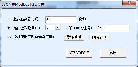
The parameters here are as follows:
1) Time of uploading to server: the every time of which JSON data is sent to the server in the default. The server is the destination IP that has just been set in the device configuration interface, and the unit is milliseconds.
2) Whether to send the device ID: if you select 1, the device ID will be included in the JSON data sent each time. The device ID is the MAC address of the device seen in the upper left corner of the device editing interface.
3) The JSON keyword of ID is the JSON keyword corresponding to the ID named by the user. “MyID” is written here and the maximum is 32 bytes. This will add the content of "MyID":"2850002F0EEC" to the JSON format later. This is similar to a registry, which helps the server identify which device sent the data.
4) Add/view: click to design the Modbus register or to view the current contents.
5) Delete all: delete all Modbus registers designed by the "add/view" button to facilitate the redesign.
6) Save JSON Settings: after the design is completed, only by clicking this button can the data be saved to the previous download directory, and then it can be downloaded to the device.
Now click the add/view button. For the first row of the previous Modbus table:
| Register address | Parameter name | Byte length | Remark |
| 0 | Current total active power | 4 | Unsigned, keeping 2 decimal places. |
The corresponding configuration is as follows:
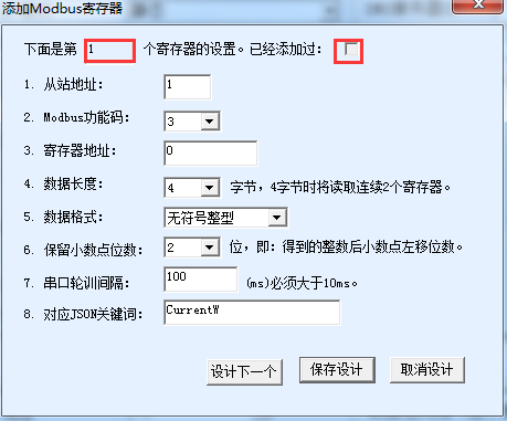
The parameters here are as follows:
1. Register 1: the 1 here indicates that the current design interface is to configure the first register.
2. It has been added: if tick means it has been added, tick will appear when viewing the configured information.
3. Slave station address: the table address of Modbus.
4. Modbus function code: currently supports function codes 03 and 04.
5. Register address: this corresponds to 0.
6. Data length: this corresponds to 4 bytes.
7. Data format: this corresponds to unsigned integer.
8. Keep the decimal point: keep two digits here.
9. Serial port polling time: set it to 100ms. The polling interval for this register and the next register, not the polling interval for this instruction.
10. Corresponding JSON keyword: corresponds to the keyword in the JSON that was sent up. For example "CurrentW":232.12.
11. Design the next one: click to enter the Settings of the next register.
12. Save the design: after completing the design, click "save JSON configuration" in the previous interface.
13. Cancel design: cancel all current designs. If you want to view the design content, you can click this button to exit.
Click the "design next" button here to continue to design the other registers in the Modbus table. After all the registers in the table are designed, click "complete the design", and then click "save JSON configuration" to exit. Then click the download button on the download web page.
Then click ok and the device will restart automatically. If there is no restart, restart manually.
Here Modbus Slave is used to simulate a table
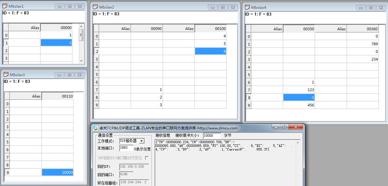
Test results show that the instrument simulated by Modbus slave tool can be collected by the gateway. At the same time it can be timed, sent to SocketDlgTest simulation server software side according to json format.
MQTT can be used alone or in conjunction with JSON functionality. When used alone, the MQTT function can transmit serial data to the MQTT server transparently. That is, the data received by the serial port is used as the payload of the MQTT. At the same time, the MQTT payload will be output from serial port via transparent transmitted. Implement serial port to MQTT.
Click "firmware and configuration" to pop up the dialog box of configuration download and design:
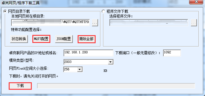
Select "web directory download" here, and then select an empty directory, such as MQTTHTTPD directory, and then click "clear all" first to clear the previous design (note that if you have previously designed according to JSON, do not clear all, otherwise it will clear the previous JSON design). Then click the MQTT configuration.
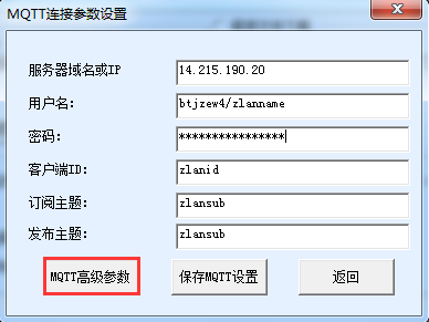
Here are the configuration instructions:
1) Server domain name or IP: the IP of the MQTT server is entered here, up to 30 characters.
2) User name: is the user name of the MQTT server.
3) Password: is the user's login password.
4) Client ID: is the client ID of MQTT.
5) Subscription topic: this is the topic that this device subscribes to. When other devices publish this topic, the server will issue it to this device. If you're just publishing, you don't usually need to fill out this field.
6) Publish topic: the topic of the data that this device sends to the server when it is serialized to MQTT.
7) MQTT advanced parameters: used to configure advanced parameters.
8) Save MQTT Settings: click this button to save after the design is completed, and then click the "download button" in the webpage download directory to download.
Now click "MQTT advanced parameters" (generally no need to configure advanced parameters) :

The instructions are as follows:
1) Protocol version: the current mainstream version is 3.1.1. If you need to select version 3.1, please select it here.
2) Survival time: the minimum heartbeat time of MQTT is 10 seconds, and the default is 60 seconds.
3) Server clear subscription: whether the server clears subscription information after the client is disconnected.
4) Whether to enable a will: whether to have a will.
5) Last will theme: last will theme.
6) Last will message: the message of last will.
7) Whether to save a will: whether the server need to keep the client's will message sent to the client when it goes offline unexpectedly.
8) Bucket quality: the quality level of delivery of bucket messages sent by the server.
9) Subscription quality: the delivery quality level of a subscription. In some cases, it needs to be set to 0 to prevent the retransmission from breaking the line.
10) Publish quality: the level of delivery quality at which a client publishes a message. In some cases, it needs to be set to 0 to prevent the retransmission from breaking the line.
11) Save publish: whether the server keeps the last message (sent to the client if there is a new client subscription).
We do not modify advanced parameters here. Click "save MQTT Settings" directly. And then click download
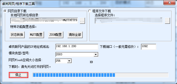
Click ok when the download is completed, and the device management dialog box will be returned. It can be seen that the destination IP, working mode and destination port of the device have been changed to MQTT automatically:

If there is no automatic modification, you need to set the destination IP, working mode and destination port under the device editing dialog box. Then click "modify Settings".
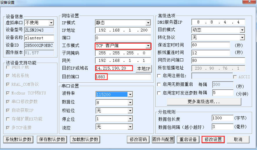
This completes the configuration.
After the connection is completed, the LINK light of the device (usually the blue light in the middle) turns on. Indicates that the device is properly connected to the MQTT server.
Now open the serial port tool:
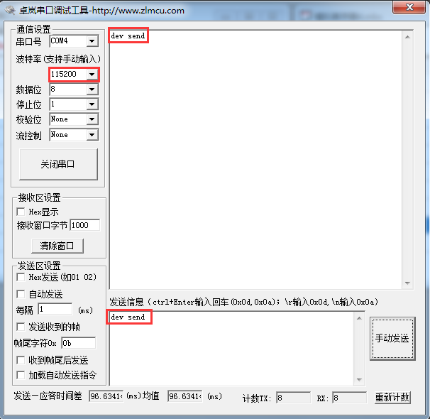
Open the serial port with the same baud rate as the device and send the data "dev send", and then see the returned data "dev send" in the receive window. This is because we are publishing this information “dev send” sent to the MQTT server under the theme of zlansub. But at the same time, our device also subscribes to the topic of zlansub, so the server will immediately send us a subscription message, and the content of the subscription message is “dev send”. This information is downloaded as a payload to the MQTT and output from the serial port via transparent transmission.
If other devices post information, the device can also receive the data.
In general, users can directly transmit serial port instructions (such as Modbus RTU) instructions directly to the MQTT server. In addition, the JSON function can also be used for automatic Modbus RTU format collection and regular JSON format sending. In addition, we can also ask Shanghai ZLAN to customize some non-standard instruments and upper computer protocol format.
Combining the above JSON and MQTT can achieve the following functions:
1) Connection is established between the protocol based on MQTT and the server, and data communication is conducted in the form of subscription publication.
2) Modbus RTU register support independent design and automatic acquisition.
3) Support for converting specific Modbus register contents into JSON format for timing active uploads.
4) Support to add device ID in JSON format to facilitate the identification of devices in the cloud.
If the function of MQTT+JSON to Modbus RTU is needed, MQTT and JSON can be designed separately, in no order. Don't click the "clear design" button after designing one, click the "download" button together to download the device content after designing two.
Generally, you can restart the device manually and load the Settings after downloading.