- +86 13512168749
- oversea@zlmcu.com
- Buy Online

关注官方微信


Products


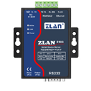
 Single Serial Device Server
Multi Serial Device Server
IoT Chip
P2P Networking Products
Serial Port Ethernet Core Module
Serial Port Ethernet Module
WIFI Products
2G/3G/4G Products
Zigbee/RF Products
Optical Fiber Products
Modbus Gataway
Remote IO Controller
Interface Converter
Single Serial Device Server
Multi Serial Device Server
IoT Chip
P2P Networking Products
Serial Port Ethernet Core Module
Serial Port Ethernet Module
WIFI Products
2G/3G/4G Products
Zigbee/RF Products
Optical Fiber Products
Modbus Gataway
Remote IO Controller
Interface Converter

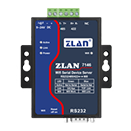
ZLAN Cloud is a free cloud platform of Internet of Things (IOT), which can collect, monitor and remotely control the data of remote devices. It can dock ZLAN6844 (analog digital volume collector), ZLAN5143 (serial port server), ZLAN8303-7 (4G DTU), ZLAN7144 (wifi / Ethernet serial port server), ZLAN7146 (wifi serial port server) and other products of ZLAN.
The cloud and equipment adopt JSON format for data transmission, and any equipment conforming to this specification can dock with ZLAN Cloud platform.
1. Add a device and select its location so that the device can be found on the map.
2. It can store the historical data of the device and display it in curves.
3. For data setting alarm value, if the alarm value exceeds the alarm value, SMS alarm can be sent.
4. Remote control of equipment, such as IO control, relay control, sending control instructions, etc.
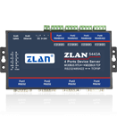
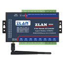
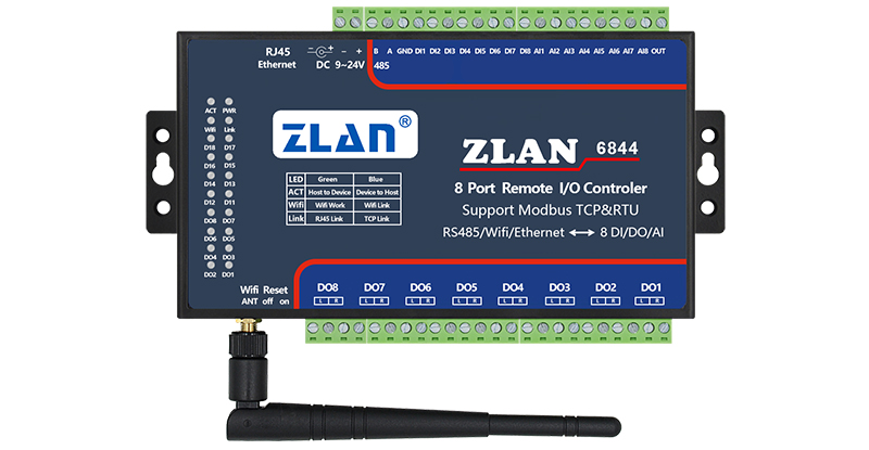
Here's how the device sends the data to ZLAN Cloud and displays it. Here to ZLAN6844 data collector as an example to introduce the use of methods. 6844 is an 8-way digital data input, analog data input and digital data output collector. The acquired analog data can be in the form of 4 ~ 40mA and 0 ~ 5V, etc. Here, the 0~5V sensor is connected to the analog input terminal AI1 ~ AI3 of 6844. The default is to use Modbus RTU instruction to collect data. What we need to do next is to convert the Modbus RTU instructions of AI1 ~ AI3 into JSON format.
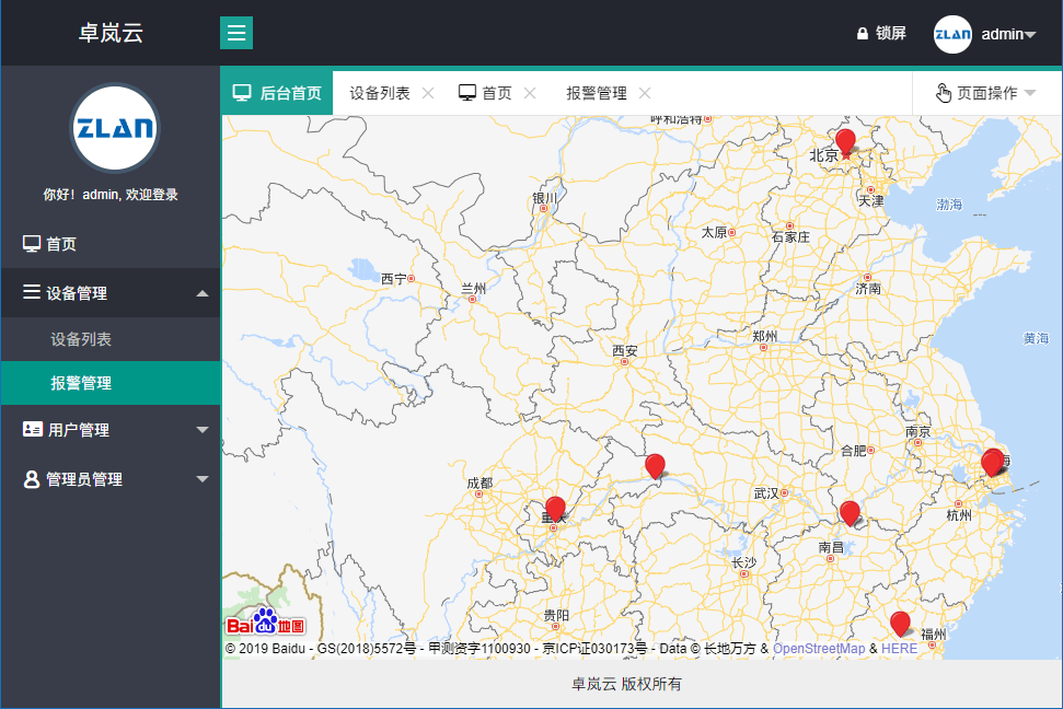
Before we can use and configure the device, we must first register the device in the cloud. Assume that the user has already obtained a user account and password from ZLAN. Please use this account and password to login to ZLAN Cloud platform.
After logging in, the map is displayed. Please right-click at the appropriate location on the map to add your device, and click the location is the location of the device. Pop up the "Device Add" dialog box:
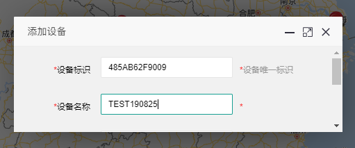
The device ID here is the unique device ID, currently the device ID, 12 characters. How to get the ID is described later, assuming 485AB62F9009. The device name is an easy name to remember. Then scroll down and click the add button.
Found an additional red dot on the map indicating that a new device has been added. Click the red dot to view device details. Click on the Device List to see the device you just added.
In this way, even after the cloud registration is completed, three parameters need to be provided by default, whose JSON keywords are POWER1, POWER2 and Power3. Therefore, the JSON format uploaded by a device must contain the following contents:
{"power1": "1019","power2": "0","power3": "0","deviceID": "485AB62F9009","acquisitionTime": "2019-08-25 14:15:57"}
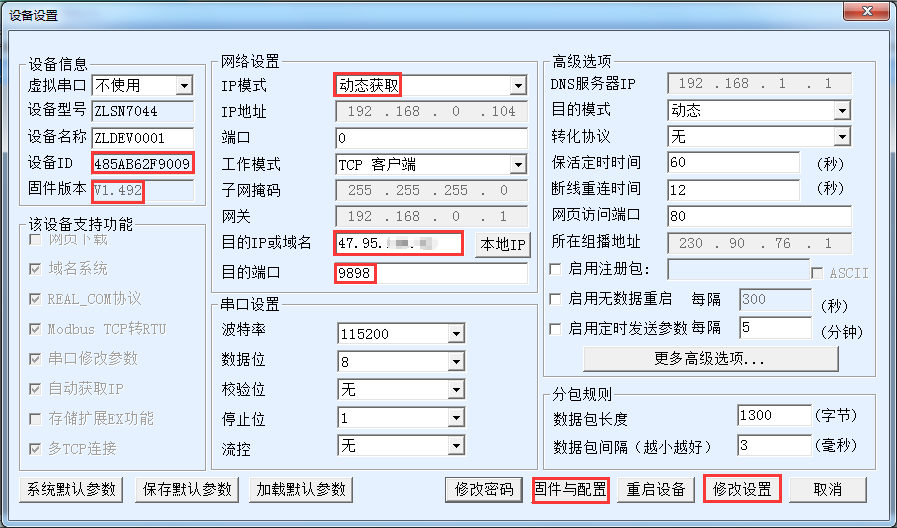
1. The device ID shown here is the ID that needs to be added to the cloud before, and the ID of each device is unique.
2. Confirm that the firmware version of 6844 is 1.492 or above.
3. Dynamic fetch is recommended for IP mode.
4. Fill in ZLAN Cloud's IP address or domain name in the destination IP or domain name.
5. The destination port defaults to 9898.
6. First click "Modify Settings" to save the parameters, and then go back to the interface and click "Firmware and Configuration" button.

First, create an empty directory 2003_default_temp. Get the NTP.txt file from ZLAN and place it in this directory. Otherwise, I am not able to get it. Then select "Web directory Download" from the above screen and select the new directory. Then click the JSON Configuration button.
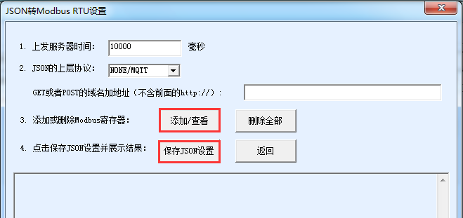
As shown in the figure, here is the option to upload pure JSON format data once in 10 seconds. Here, first click "Add/View" button, and then click "Save JSON configuration" when you return to this interface after configuration. Now click the "Add/View" button:
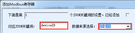
1. Add JSON of device ID:
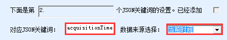
2. Then click the "Design next" button, and design to get time JSON:
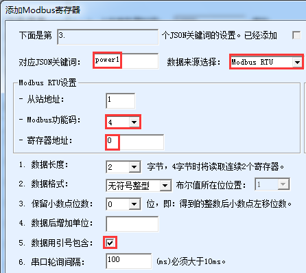
3. Then click the "Design the next" button to design the data collection of AI1. Since AI1 adopts the Modbus function code of 04 with the address of 0, the configuration is as follows:
4. Then click the "Design next" button to continue adding JSON for AI2 and AI3. For AI2 and AI3, just change the register address to 1 and 2, and change the JSON keyword to POWER2 and POWER3. Note that when designing AI3, do not click "Design next" but click "Save design".
Configuration" interface, click "Download" button, and download the configuration to the device.
At this point, can see the LINK light of ZLAN6844 turn blue, indicating that the connection is established with the server, and ACT blue and green flashing indicate that the data collection is in progress.
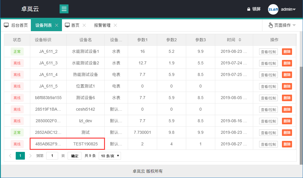
Log in ZLAN Cloud and see that the parameters 1, 2 and 3 of TEST190825 correspond to POWER1, POWER2 and POWER3, which are the latest data.
Click the "View/Control" button on the right to see the curve of the historical data:
In addition, you can also set the time range of historical data query, set the instruction, etc.
This paper introduces how to use ZLAN6844 to transmit sensor data to ZLAN Cloud from two aspects of cloud registration and equipment configuration. ZLAN equipment and cloud cooperation will systematically solve the sensor cloud, equipment alarm, remote control and other problems.
In addition, we provide the following services:
1. Deploy your own private cloud service to your customers at an affordable price.
2. Provide cloud docking protocol analysis for all kinds of non-standard sensors and RS485 protocols for customers.
3. Customized development of specific cloud server interface and data according to user requirements.